
I've just finished my second year of software development school, and now I finally have time to write, create, and hopefully rest. I have 6 weeks of summer vacation, and I've decided to start a mini-series called "Vac Week" where I'll (hopefully) post one article per week, covering a variety of subjects — obviously tech-related.
In this first episode, I'll document and explain how I've managed to make a USB stick boot to life, how I like to call it, or less spectacularly "boot into Conway's Game Of Life without any OS, and keep the culture alive."
Without further ado, let's start by making a small checklist of the steps I've gone through, and that I'll cover in this article.
- Figuring how to create something that boots
- Go from 16 to 32 bits
- Run C code
- Integrate the Game Of Life
- Make the game better
Figuring How to Create Something That Boots
I didn't even start to write a single line of code and I'm already facing a dilemma: should I go the legacy route, or the multiboot one?
Let's break down what this means: the good old way of making a bootable binary is writing code — often assembly — that'll end up in the first 512 bytes of your drive, and that the BIOS will detect, load, and execute.
The multiboot route skips a lot of hard work. You hand the startup to a boot manager such as GRUB, and it loads the code present on your drive, if any.
If you already read some of my other articles, you can guess that I'll go with the first one — where's the fun in doing it the easy way? And I already have some assembly knowledge (you don't need to, don't worry).
So before doing anything complicated, I wanted to start with the good old "Hello, world!".
And to do so, I'll use the BIOS. As you may know, the BIOS, beside loading our program, also acts as glue that holds the lowest level way to interact with different components on our motherboard, such as the screen, keyboard, etc. And the BIOS also exposes functions, that we can use directly via BIOS interrupt calls.
To display a hello world, I'll need to make a loop, that tells the BIOS to display our string character by character.
Before diving in, a bit of theory. To know if a drive is bootable, the BIOS will look at bytes n°511 and 512 of your drive, and look if it contains the signature 55 aa. This is required to be at exactly those bytes so the BIOS recognizes your drive as bootable. After that, the BIOS loads bytes 1 to 512 into the RAM at a fixed memory address: 0x7C00. At this stage, everything is running in 16 bits for backwards compatibility.
Let's start coding. As the code is in assembly (for now, we'll make it switch to C later!), I'll try to make it as understandable as possible.
Let's start by telling NASM (our compiler) that we're at address 0x7C00, and in 16 bits.
[org 0x7C00]
[bits 16]
Now, we can directly start printing our string:
start:
    mov si, msg  ; SI = pointer to our string

print_loop:
    lodsb           ; load byte at [SI] into AL, increment SI

    cmp al, 0       ; check if AL is 0 (end of string)
    jz done         ; if zero, we're done

    mov ah, 0x0E    ; BIOS teletype function
    int 0x10        ; BIOS video interrupt

    jmp print_loop
Without getting too technical, what this does is point si — a 16-bit CPU register, see them as small memory addresses on which you can do operations — to msg, a variable loaded into the RAM containing our hello world. It then loops until it's reached the end of the string (byte 0). To write the character, it uses the BIOS function 0x0E that basically prints the content of the al register to the screen.
Finally, when it's finished printing, it loops forever:
done:
    jmp $  ; infinite loop
$ contains our current address, so jumping to it means jumping to where we are (the jump instruction), and it goes like that forever.
Let's now define our msg var:
msg db 'Hello, World!', 0
At the very end of the file, we add this:
times 510-($-$$) db 0  ; pad to 510 bytes to set the magic bytes
dw 0xAA55              ; boot signature BIOS looks for
Which adds as many zeroes as needed until we're at byte 510, and closes with the signature the BIOS expects.
Testing it
To test my programs — and to not have to flash a USB stick each time — I use QEMU, an open source machine emulator and virtualizer.
Let's try:
nasm -f bin hello.asm -o hello.bin # compile our code to a binary

qemu-system-x86_64 -drive format=raw,file=hello.bin # boot the raw binary
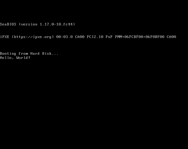
And it looks like it worked!
-
Figuring how to create something that boots
Now, let's go deeper.
Go from 16 to 32 Bits and Load Actual Code
You thought I'd passed the hard part? WRONG. What I went through after this was literal HELL. If you want to escape and skip this part, click here.
See, the small hello world program I made was 16 lines. The next one is 6 times bigger, and 80 times more complex.
Here is what I did:
- I started by loading 20 sectors (1 sector = 512 bytes) from my disk, to load my future C code. You probably can guess that it won't fit in 512 bytes.
- Next, I directly switched video mode (basically how you interact with the display) to VGA 13. It is a graphic mode with a 320x200 layout, and 256 colors. It is really easy to interact with it since you simply set a byte per pixel, starting at memory address
0xA0000. - I loaded the GDT table, which I'll explain later more in details.
- Finally, I enabled the CPU protected mode, and jumped to the code I previously loaded from disk.
1. Loading sectors from disk
This is still a relatively easy task, the BIOS exposes a function (0x02) that lets us load sectors to a specific memory address:
load_sectors:
    ; Read kernel sectors from disk into memory

    ; int 0x13, ah=0x02 (read sectors)
    mov ah, 0x02
    mov al, 20          ; number of sectors to read
    mov ch, 0           ; cylinder 0
    mov cl, 2           ; start at sector 2 (sector 1 is this boot sector)
    mov dh, 0           ; head 0
    ; dl already holds boot drive number, set by BIOS
    mov bx, 0x1000      ; es:bx = load address
    int 0x13

    jc .disk_error      ; carry flag set = read failed
    jmp switch_vga_vid
As the comments specify, we read 20 sectors (20*512 = 10.24KB) of our current drive into address 0x1000, supposing they hold our code.
2. Switching video mode
This is also easy, just a few lines telling the BIOS to change it:
switch_vga_vid:
    ; Switch to VGA mode 13h (320x200, 256 colors)

    ; int 0x10, ah=0x00 (set video mode)
    mov ah, 0x00
    mov al, 0x13
    int 0x10
3. Loading the GDT table
This is the hard part. Protected mode won't let the CPU touch memory freely — it needs to be told upfront what memory exists and how it can be used. That's what this table, the Global Descriptor Table (GDT), is for.
Every GDT needs at least 3 entries:
- A null entry (required, the CPU just wants it there)
- A code segment (for executing instructions)
- A data segment (for reading/writing data)
Each entry is 8 bytes, packed into a slightly awkward layout for historical reasons: base address, limit (size), and access flags, split and reordered across the 8 bytes instead of laid out cleanly. Here's how I set mine up:
gdt_start:

gdt_null:
    ; first entry must be null, CPU requires this
    dq 0x0

gdt_code:
    ; code segment descriptor
    dw 0xFFFF     ; limit (bits 0-15)
    dw 0x0        ; base (bits 0-15)
    db 0x0        ; base (bits 16-23)
    db 10011010b  ; access: present, ring 0, code, executable, readable
    db 11001111b  ; flags + limit (bits 16-19): 4k granularity, 32-bit
    db 0x0        ; base (bits 24-31)

gdt_data:
    ; data segment descriptor, same as code
    dw 0xFFFF
    dw 0x0
    db 0x0
    db 10010010b  ; access: present, ring 0, data, writable
    db 11001111b
    db 0x0

gdt_end:
Both segments start at base 0x0 and span the full 4GB (thanks to the 11001111b flags byte, which sets 4K granularity). This is called a "flat" memory model — segmentation is disabled, since every segment sees the entire address space the same way.
The only real difference between the code and data descriptor is the access byte: 10011010b marks it executable, 10010010b marks it writable instead.
Once the table is defined, the CPU needs to know where it is and how big it is, so let's build a descriptor for the descriptor table:
gdt_descriptor:
    dw gdt_end - gdt_start - 1  ; size of GDT, minus 1
    dd gdt_start                ; address of GDT

CODE_SEG equ gdt_code - gdt_start  ; selector for code descriptor
DATA_SEG equ gdt_data - gdt_start  ; selector for data descriptor
CODE_SEG and DATA_SEG are just offsets into the table — they're what you load into the segment registers later to say "use this descriptor."
Loading it into the CPU is a single instruction:
load_gdt:
    lgdt [gdt_descriptor]
lgdt tells the CPU "here's your new GDT, go read it."
4. Switching to protected mode
This is the last step everything else was building toward. Basically, I'm telling the CPU "stop behaving like a 1978 processor — including its limitations: 16 bits registers, 1MB of addressable memory, no protections — and give me actual stuff to work with: 32 bits registers, 4GB of protected memory (requires the GDT I setup earlier). Well, since I'll run a standalone program with no user input, I don't care about the protection, but I do care about the other stuff :D.
Actually, if everything is setup correctly, switching to protected mode is as easy as switching a singular bit, the PE (protected enable) bit, in the register cr0 (control register 0).
enter_protected:
    mov eax, cr0
    or eax, 1     ; set PE bit, leave every other bit untouched
    mov cr0, eax

    jmp CODE_SEG:protected_mode_start  ; far jump flushes the prefetch queue
And I'm done! As you might have seen, the last jmp instruction isn't a normal one, it's a far jump. See, the CPU instruction prefetch queue might still hold real-mode (the old one) decoded bytes, a far jump forces it to flush that queue.
Last, protected_mode_start cleans everything up, and jumps to the code I previously loaded to 0x1000:
[bits 32]
protected_mode_start:

    ; Reload segment registers with the flat data selector now that
    ; segmentation means something different in protected mode
    mov ax, DATA_SEG
    mov ds, ax
    mov es, ax
    mov fs, ax
    mov gs, ax
    mov ss, ax

    mov esp, 0x90000  ; fresh 32-bit stack

    jmp 0x1000        ; jump to the loaded kernel
Phew, now I'm chilling, the hard work has been done. Let's switch to more enjoyable programming.
-
Go from 16 to 32 bits
Writing a C Kernel
From now, I should be able to write code in C. Hooray.
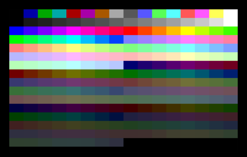
And more specifically, I'll write a kernel, but probably not the one you're thinking of. You might think of the Linux kernel, or the Windows NT kernel. However, all a kernel is, is the piece of code that the bootloader (that we just wrote) hands control to. In my case, I wrote a small piece of C code that prints every default indice of the 256 colors palette:
typedef unsigned char u8;

u8 *vga = (u8*) 0xA0000;  // mode 13h framebuffer, 320x200, 1 byte per pixel = palette index

void kmain() {
  for (int color = 0; color < 256; color++) {
    int x_start = (color % 16) * 20;   // 16 columns
    int y_start = (color / 16) * 12;   // 16 rows

    for (int y = 0; y < 12; y++) {
      for (int x = 0; x < 20; x++) {
        int px = x_start + x;
        int py = y_start + y;
        vga[py * 320 + px] = color;  // write palette index directly
      }
    }
  }

  for (;;) { }  // halt forever
}
Note that I literally have nothing backing me up. The libc does not exist in my program, if I need something, I'll probably need to implement it from scratch.
Also, I use kmain for kernel main, but it's the same as using main. Or pepito.
Wiring Everything Together
You can probably guess that putting everything together isn't as easy as simply
nasm -f bin boot.asm -o boot.bin
gcc kernel.c -o kernel.bin
cat boot.bin kernel.bin > image.bin
I need to add some glue to those different parts instead of smashing them together. And that is basically the linkers job.
What I want is the bootloader, in assembly, to be able to recognize and jump to the C kmain() function. However, that is not possible yet.
What I'll do instead, is jump to another assembly program, that will be linked with the C program, so it knows what to launch.
The assembly itself is probably the most simple assembly code you'll ever see:
[bits 32]

extern kmain
global _start

_start:
    call kmain
    jmp $
Basically, extern tells the nasm compiler that it'll later be linked with a program containing the kmain function.
And that's exactly what I'll do:
# compile
nasm -f elf32 load_kernel.asm -o load_kernel.o
gcc -m32 -ffreestanding -fno-pie -c kernel.c -o kernel.o

# link
ld -m elf_i386 -T linker.ld --oformat binary load_kernel.o kernel.o -o kernel.bin
All the gcc flags are there to tell it not to make assumptions, and that it won't be running in any environment it recognizes.
The part that interests us is the ld command, that will link and convert both object files to a kernel.bin binary file.
The linker.ld is simply a file to ensure everything goes at the right place:
ENTRY(_start)

SECTIONS
{
    . = 0x1000;  /* load here */

    .text   : { *(.text) }
    .data   : { *(.data) }
    .rodata : { *(.rodata*) }
    .bss    : { *(.bss) *(COMMON) }
}
The last step before effectively smashing the two glued pieces together is this:
truncate -s 10240 kernel.bin
This will pad the generated kernel.bin to 10240 bytes with zeroes. Why? Simply because I chose to load 10240 bytes in my bootloader, and it will crash if those bytes do not exist.
Once I applied glue to all the pieces, I can put them together:
cat boot.bin kernel.bin > image.bin
Full build script
#!/bin/bash
# builds the boot binary composed of boot.asm, load_kernel.asm, and kernel.c

set -e

# compile
nasm -f bin boot.asm -o boot.bin
nasm -f elf32 load_kernel.asm -o load_kernel.o
gcc -m32 -ffreestanding -fno-pie -c kernel.c -o kernel.o

# link
ld -m elf_i386 -T linker.ld --oformat binary load_kernel.o kernel.o -o kernel.bin
truncate -s 10240 kernel.bin # to match load_sectors sectors size

# assemble
cat boot.bin kernel.bin > image.bin

# delete stuff we dont really want
rm boot.bin load_kernel.o kernel.o kernel.bin
Trying the New Kernel
And now I can finally try what I spent hours to assemble and debug. Let's run this into QEMU, and look at this:
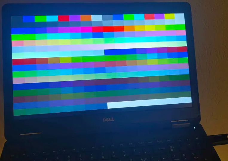
And this is also going to be the first time I tested it on real hardware. I picked up an old dell latitude laptop, and a USB stick.
Flashing the stick is easy:
# in my case, /dev/sda is the USB stick. If you reproduce it, be sure to not wipe another disk with important data such as your OS!
sudo dd if=image.bin of=/dev/sda bs=512
Then I just plugged it into the laptop, smashed F8, selected it, and look at this beauty:
-
Run C code
Implementing the Game of Life
Now that the hard part's done, let's do the light work. All we gotta do is implement the Game of Life algorithm. To do so, I simply took André Jesus implementation, as it has been released license-free, and I wont reinvent the wheel this time. Plus his implementation is really well-made, with a toroidal grid and the ability to tweak the rules, that we'll explore a bit later.
All I did on the engine was removing functions I didn't need (such as writing files into an inexistent filesystem), and replace the display function.
Originally, the main display mode was printing to stdout using this function:
void fprint_world(const int world[][MAX_COLS], int rows_count, int cols_count, FILE *__restrict__ __stream)
{
  for (size_t row = 1; row < rows_count + 1; row++)
  {
    for (size_t col = 1; col < cols_count + 1; col++)
    {
      fputs((world[row][col]) ? "X " : ". ", __stream);
    }
    fputc('\n', __stream);
  }
}
with __stream being STDOUT.
That said, I wanted to display it on my VGA output, so I ended up making a bigger but much better function:
void display_world(u8* vga, const int world[][MAX_COLS], int rows_count, int cols_count)
{
  int cell_size = 2;

  for (size_t row = 1; row < rows_count + 1; row++)
  {
    for (size_t col = 1; col < cols_count + 1; col++)
    {
      int color = get_cell(world, row, col) ? 15 : 0;  // white if alive, black if dead

      int x_start = (col - 1) * cell_size;
      int y_start = (row - 1) * cell_size;

      for (int y = 0; y < cell_size; y++)
      {
        for (int x = 0; x < cell_size; x++)
        {
          int px = x_start + x;
          int py = y_start + y;
          vga[py * 320 + px] = color;
        }
      }
    }
  }
}
What it basically does is setting every 2x2 pixels to either black (0) or white (15), depending on the cells state, by updating the byte at the corresponding memory address.
With that in place, I made a new kernel.c — starting by specifying the classic rules: die with more than three neighbors or fewer than two neighbors, and spawn with three neighbors.
Then, I seeded a glider, and made a loop:
- display the world
- update the world
- wait some time
The "hard" part was the time waiting, since we do not have the libc usleep function. So what I did instead, is waiting N cpu cycles to elapse. This works, but is approximate, since every CPU works at different speeds. For instance, my qemu VM runs at 128ms/gen, while the old laptop runs at 93ms/gen.
int kmain(void)
{
  int rows_count = 100;
  int cols_count = 160;

  int rule[RULE_SIZE] = {3, 2, 3};  // {maxNeighbors, minNeighbors, neighborsToBorn}

  static int world[102][MAX_COLS];
  static int world_aux[102][MAX_COLS];

  clear_world(world, rows_count, cols_count);

  // seed a glider
  set_cell(world, 1, 2, 1);
  set_cell(world, 2, 3, 1);
  set_cell(world, 3, 1, 1);
  set_cell(world, 3, 2, 1);
  set_cell(world, 3, 3, 1);

  while (1)
  {
    display_world(world, rows_count, cols_count);
    update_world(world, rows_count, cols_count, world_aux, rule);

    // this is like "wait for the CPU to do N cycles before continuing"
    // so the game speed will depend on the CPU speed
    int wait = 40000000;
    for (volatile unsigned int i = 0; i < wait; i++);

  }

  return 0;
}
And it works perfectly!
-
Integrate the Game Of Life
Make the Game Better
Now that I've got a working engine, let's make it better. What I mean is that I currently only have a glider, walking around. Let's make it more interesting to watch.
I'll divide that into three subtasks:
- Add ageing
- Add random spawning
- Add stats
Add Ageing
This was fairly easy, at least on the engine side. See, cells are stored as numbers, previously 0 for a dead cell, and 1 for an alive cell. All I did is make them go from 1 to 20, incrementing the number each generation that a cell survives.
On the display side though, it was a bit harder. I wanted to make the cells change color each time they aged, but I had an issue: the VGA default palette the BIOS ships with is really limited. That meant I had to overwrite it. To do so, I need to talk to the VGA DAC (Digital to Analog Converter) table to set my custom palette, and this is done by writing to those hardware registers addresses:
void outb(u16 port, u8 val) {
  asm volatile("outb %0, %1" : : "a"(val), "Nd"(port));
}

void set_palette_color(u8 index, u8 r, u8 g, u8 b) {
  outb(0x3C8, index);
  outb(0x3C9, r);
  outb(0x3C9, g);
  outb(0x3C9, b);
}
Then I just loop for 20 colors, going from yellow to dark red (or yellow to pink / magenta in some newer versions):
for (int i = 0; i <= 20; i++) {
  u8 r, g, b;

  // this linearly interpolates R/G/B across three bands
  if (i < 7) {
    // yellow -> orange
    r = 63;
    g = 63 - (i * 20) / 7;
    b = 0;
  } else if (i < 14) {
    // orange -> red
    int j = i - 7;
    r = 63;
    g = 43 - (j * 43) / 7;
    b = 0;
  } else {
    // red -> dark red
    int j = i - 14;
    r = 63 - (j * 40) / 6;
    g = 0;
    b = 0;
  }

  set_palette_color(i + 1, r, g, b);
}
VGA DAC registers are 6-bit, that's why we go up to 63, and not 255.
All we need to do after this is write a small helper function in the GoL engine:
int age_to_color(int age)
{
  if (age <= 0)
    return 0;

  int max_age = 20;
  if (age > max_age)
    age = max_age;

  return age + 1;
}
And update the display function to take it into account:
int color = age_to_color(get_cell(world, row, col));
// [...]
    vga[py * 320 + px] = color;
Finally, I replaced the glider with a square to see the cells age.
-
Add ageing
Add Random Spawning
Having a cube, a glider, or a predefined setup is nice, but having random spawning would be better.
Sadly, I obviously don't have rand, so this time I'll implement it myself.
To get my first seed, I'll use the number of cycles the CPU went through since the last boot, which is enough for my needs. I'll then use it to start a LCG, which is a pseudo-random number generator engine I used in this article.
static unsigned int rng_state;

unsigned int read_rdtsc_low(void)
{
  unsigned int lo, hi;
  asm volatile ("rdtsc" : "=a"(lo), "=d"(hi));
  return lo;
}

void seed_rng(unsigned int seed)
{
  rng_state = seed;
}

unsigned int rand_next(void)
{
  rng_state = rng_state * 1103515245 + 12345;
  return (rng_state >> 16) & 0x7FFF;
}

unsigned int rand_int(unsigned int min, unsigned int max)
{
  return min + (rand_next() % (max - min + 1));
}
And I seed it once on program startup:
int kmain() {
  seed_rng(read_rdtsc_low());
And in the game loop, before updating the world, I toggle 100 random cells over the world:
for (volatile unsigned int i = 0; i < 100; i++) {
  int row = rand_int(0, rows_count);
  int col = rand_int(0, cols_count);

  set_cell(world, row, col, get_cell(world, row, col) > 0 ? 0 : 1);
}
I removed the initial seed, and now simply let the randomness do its work:
-
Add random spawning
Add Statistics
This may seem easy, but it's not a piece of cake. I wanted to display the current number of alive cells, and the current generation number on the top left of the screen. But there was an issue: we can't write text in graphical mode. See, VGA either supports text mode, or graphics mode (and others), but not both at once.
To counter this issue, I had to draw text, while being in graphics mode. I make it sound painful, but it really just was boring. What I basically did is take a 5x7 font I found online, and added it into a new font.c file.
A font character looks like this:
static const u8 font_0[7] = {0b01110, 0b10001, 0b10011, 0b10101, 0b11001, 0b10001, 0b01110};
And each element of the list represents a pixel in a row.
To not bloat my program too much, I only integrated numbers 0-9 and letters A (alive) + G (generation).
I then wrote a simple function to print a character:
void draw_char(u8* vga, char c, int x_start, int y_start, int color)
{
  const u8 *glyph = get_font(c); // get_font is a switch that returns the font or NULL
  if (!glyph)
    return;

  for (int row = 0; row < 7; row++)
  {
    for (int col = 0; col < 5; col++)
    {
      if (glyph[row] & (1 << (4 - col)))
      {
        vga[(y_start + row) * 320 + (x_start + col)] = color;
      }
    }
  }
}
And one to draw a full string:
void draw_string(u8 *vga, const char *str, int x_start, int y_start, int color)
{
  int x = x_start;

  while (*str)
  {
    draw_char(vga, *str, x, y_start, color);
    x += 6;  // 5px glyph + 1px spacing
    str++;
  }
}
Then simply added it to the main loop:
char alive_str[16];
char gen_str[16];

alive_str[0] = 'A';
itoa(count_alive(world, rows_count, cols_count), alive_str + 1);

gen_str[0] = 'G';
itoa(generation, gen_str + 1);

draw_string(vga, alive_str, 10, 10, 22);
draw_string(vga, gen_str, 10, 20, 22);
Note that I previously reserved id 22 for a white font:
set_palette_color(22, 63, 63, 63);
And done!
-
Add stats
Making better spawning
This wasn't on my list initially, but after some time I've witnessed some issues with the current implementation of random spawning. See, it was great for adding a lot of life, but since it was generating a lot of noise, organisms didn't have the time to make stuff before randomly getting destroyed by a cell flip. It was pretty frustrating seeing a beautiful thing being created then destroyed the next generation.
So I've come to a pretty nice solution: instead of toggling a fixed amount (100) of cells, I've made it adaptive:
- If there is currently less than 100 cells alive, we toggle 150 cells per generation
- If there is more than 100 cells, but less than 500 cells alive, we toggle 50 cells per generation
- If there is more than 500 cells, but less than 1000 cells alive, we toggle 10 cells per generation
- If there is more than 1000 cells, we don't toggle any cell
This model — that I tuned by hand — is pretty nice, since it keeps our cell culture alive, without it being too chaotic. It stabilizes at around 1000 cells after some time, since cells tend to extinguish without external events (no toggles).
-
Make the game better
Finally
After about 3 days of working on this project, it finally got to a point where I think it can be called finished. I've learned a lot of things on this journey, and hope that you too, if you're still reading this.
Here is the final version, at the time I'm writing this article:
One of my favorite things about looking at this is spotting little gliders walking around from time to time — you can spot two of them at 0:32 — and also seeing cool patterns that disappear after two seconds.
Additionally, while playing a bit with the game's settings, I've managed to make this, by settings the rules to {4, 1, 2} instead of {3, 2, 3} — still in the {maxNeighbors, minNeighbors, neighborsToBorn} format — and removing the better spawning logic to go back to the always 100 toggles. I find it really beautiful to watch:
Oh, and to end this article with something cool, I projected the GoL on one of my walls, using an old computer with an ASUS mobo. And omg I did struggle on getting it to boot. I had to make it consider EVERY USB device as a FLOPPY DRIVE. Now I gotta remember to switch it back.
Anyways, here's the footage:
And well, see you next week!
Comments
Leave a comment